Choosing a turning insert comes down to four decisions, taken in order: shape, then size, then nose radius, then grade with chipbreaker. Two checks follow: the insert has to fit the holder, and the numbers have to suit the machine and the setup. Take the order out and you end up with an insert that fits the holder but cannot reach the part.
Step 1 — Shape: what the profile allows
The shape letter is the first character of the ISO designation. It fixes the included angle at the tip, and that single angle decides three things at once: how tight a corner the insert can reach, how many cutting edges you get, and how much punishment the edge survives.
 C — 80° RhombicCNMG 120408
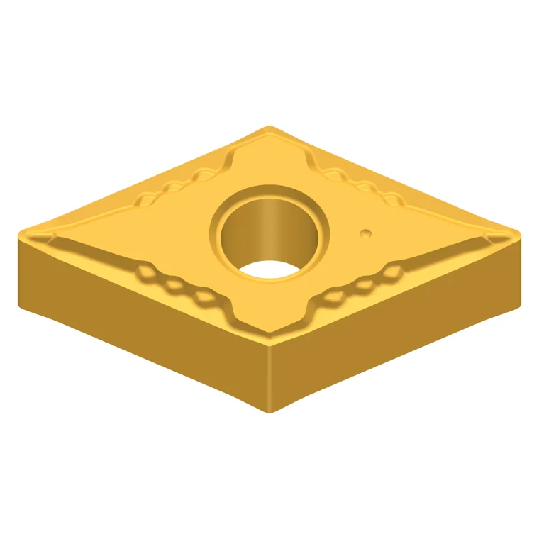 D — 55° RhombicDNMG 150608
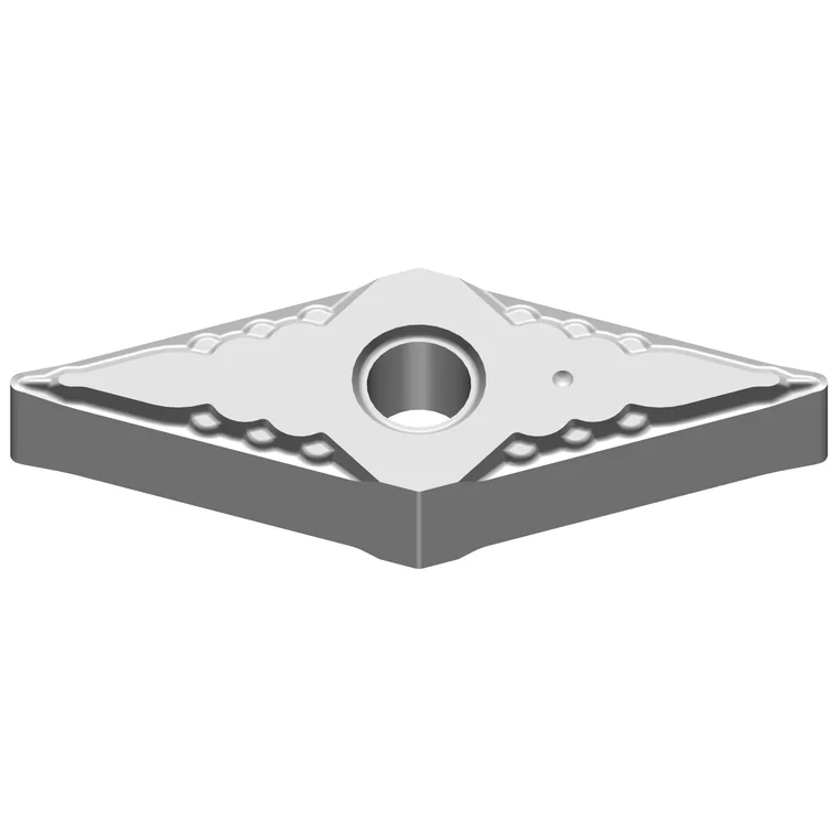 V — 35° RhombicVNMG 160404
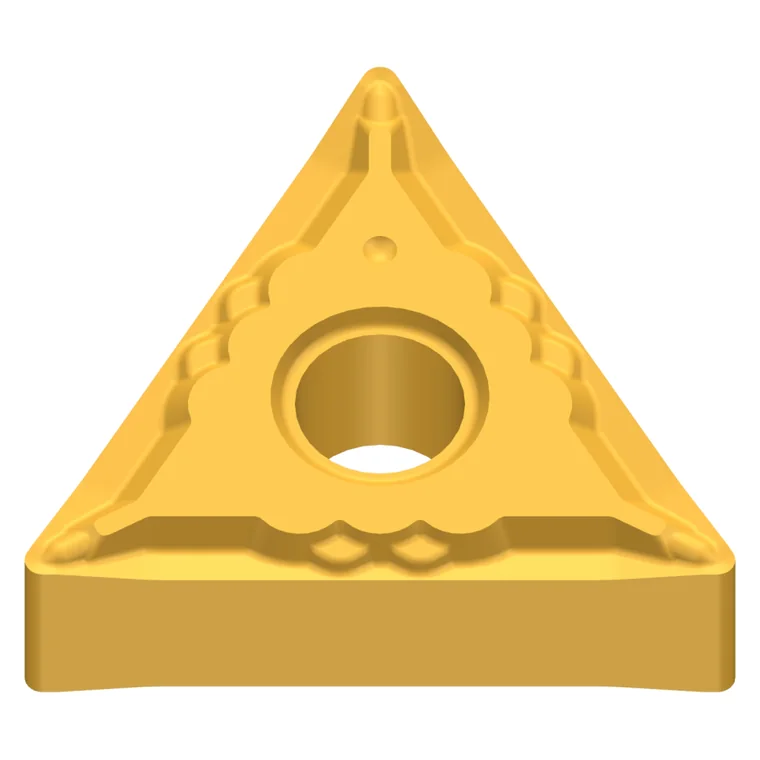 T — 60° TriangleTNMG 160408
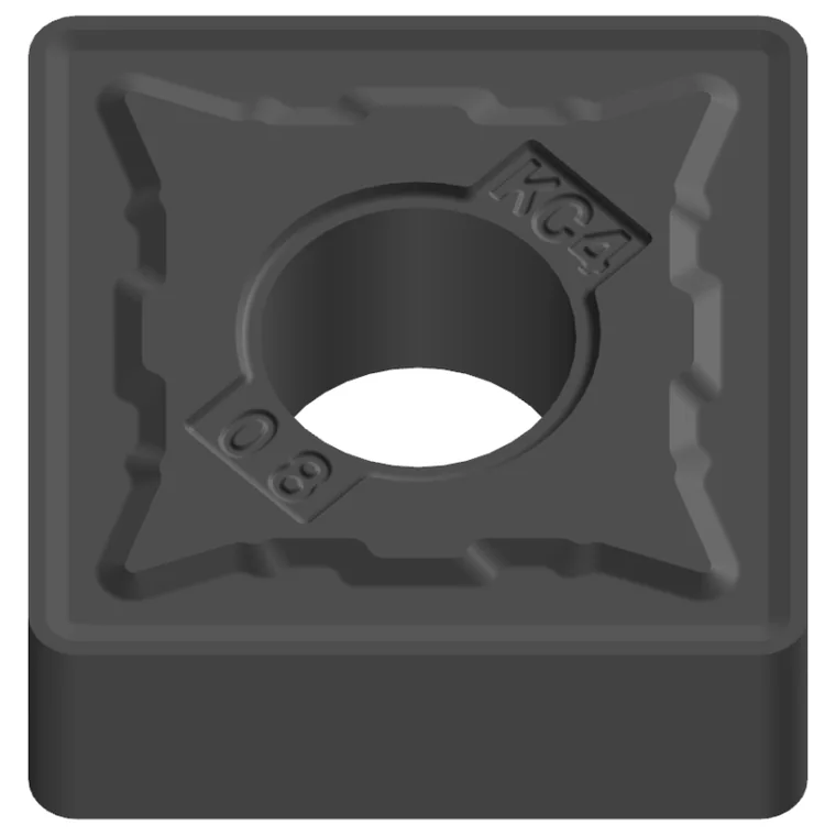 S — 90° SquareSNMG 120408
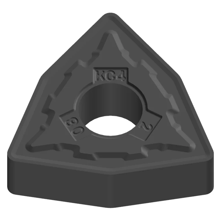 W — 80° TrigonWNMG 080408
Most turning work in a job shop is covered by six shapes. The angle is the number that matters — it is a direct trade between reach and strength.
| Letter | Included angle | Edge strength | Reach | Typical use |
|---|---|---|---|---|
| C | 80° | High | Moderate | General turning and profiling. Four edges and the widest grade choice, which is why it is the default answer for most jobs. |
| D | 55° | Medium | Good | Profiling and undercuts that a C insert cannot reach. Four edges, but a more exposed tip. |
| V | 35° | Low | Best | Fine profiling, small bores and copy turning. Four edges; the point concentrates heat, so keep it for light and continuous cuts. |
| T | 60° | Medium | Poor | Economical general turning. Six edges make it the cheapest insert per edge, but the 60° point is the weakest of the common shapes. |
| S | 90° | Highest | Poor on profiles | Heavy roughing, shoulder work and facing. Eight edges and the most rigid tip, which is what you want on scale and interrupted cuts. |
| W | 80° | High | Good | Roughing and profiling in one insert. Six usable edges and close to C strength, so it suits shops that want one insert to cover more work. |
| H | 120° | Very high | Very poor | Heavy roughing where the part has no awkward corners and edge life matters more than reach. |
| R | Round | Highest | Not applicable | Roughing hard skins, castings and long overhangs. The round edge spreads load better than any pointed shape. |
Practical ruleMatch the included angle to the tightest corner on the part, then take the largest angle that still reaches it. Everything wider than that costs you strength for nothing.
Common mistakeReaching for a 35° V insert on a roughing pass because it reaches everything. A sharp point puts the heat of the cut into a few square millimetres and will chip the moment the cut is interrupted. Reach is a finishing problem, not a roughing one.
Step 2 — Size: inscribed circle and thickness
The next two digits are a series code, not a measurement. They tell you which inscribed circle the insert belongs to — the largest circle that fits inside the shape — and the actual dimension is a standardised value close to, but not the same as, the code. The 06 series is about 6.35 mm across, the 09 series about 9.53 mm, the 12 series about 12.7 mm, the 16 series about 15.875 mm and the 19 series about 19.05 mm.
| Size series | Inscribed circle (approx.) | Typical depth of cut | Where it fits |
|---|---|---|---|
| 06 | 6.35 mm | Up to about 2 mm | Small parts, small bores, low-power lathes |
| 09 | 9.53 mm | Up to about 3 mm | General small and medium turning |
| 12 | 12.7 mm | Up to about 6 mm | The workhorse size for general turning |
| 16 | 15.875 mm | Up to about 8 mm | Heavier roughing on rigid machines |
| 19 | 19.05 mm | Up to about 10 mm | Large shafts and heavy stock removal |
Thickness works the same way. 04, 08 and 12 are series codes again: a 04 insert is about 4.76 mm thick, an 08 about 7.94 mm and a 12 about 12.7 mm. Thicker means more rigidity, but the seat in the holder has to take it, so thickness is chosen with the holder rather than on its own.
Practical ruleAs a starting point, keep the depth of cut at or below roughly two thirds of the actual inscribed circle. Read that number from the manufacturer’s dimension sheet rather than from the code — the code tells you the series, not the millimetres.
Step 3 — Nose radius: finish against strength
The last two digits are the nose radius in tenths of a millimetre: 04 is 0.4 mm, 08 is 0.8 mm and 12 is 1.2 mm. Nose radius is the cheapest productivity lever you have, because it changes both the surface finish and the strength of the tip without changing the holder or the grade.
- Small radius (0.2–0.4 mm) — fine finishing and thin walls. Cutting force is low, but the tip chips easily and the finish falls away quickly as it wears.
- Medium (0.8 mm) — the general-purpose default. This is why a CNMG 120408 is the single most stocked turning insert in the catalogue.
- Large (1.2–2.4 mm) — heavy roughing and interrupted cuts. Best heat spreading and the strongest edge, but it needs a rigid setup and enough power.
Two rules keep you out of trouble. The nose radius must be smaller than the smallest concave radius on the part, or the insert physically cannot produce the profile. And theoretical surface finish follows Ra ≈ fn² / (32 × RE): double the nose radius and you halve the roughness at the same feed, which means you can also double the feed and keep the finish.
Common mistakeUsing a 0.4 mm nose radius to rough because it is the finishing insert already in the machine. The radius that gives you a mirror finish on a light pass will break down within minutes once the depth of cut goes up.
Step 4 — Grade: start from the material group
The ISO insert code tells you the shape, the size and the nose radius. It does not tell you the grade and it does not tell you the chipbreaker. A CNMG 120408 can be a finishing grade or a roughing grade, a steel grade or a stainless grade — the designation is identical. Grade and chipbreaker are separate decisions, and they start from the workpiece.
ISO 513 sorts machinable materials into six groups. The group, not the material name, is what the grade is designed around.
| Group | Workpiece | What it does to the edge | Grades we stock for it |
|---|---|---|---|
| P | Steel | Continuous chips, high heat at the rake face | AT210A, AC152P, AC052P, AC252P, AC350P |
| M | Stainless steel | Work-hardens, notches at the depth-of-cut line | AP200U, AC200M, AC100M, AP200M, AP301M |
| K | Cast iron | Abrasive, short chips, little built-up edge | AT202, AC102K, AC202K, AP251K, AC301K |
| N | Aluminium and non-ferrous | Soft, sticky, tends to weld to the edge | PD20, HS6120, HS7125, HS8115 |
| S | Superalloys (Inconel, titanium) | Extreme heat, strong work-hardening | AP100S, AP351M, AP403M, AC200M |
| H | Hardened steel | Very high cutting force, hard and abrasive | PB30, PB60, AP151H, AP153H |
Inside a group, grade is a three-way trade between wear resistance, toughness and coating. That maps onto the finishing / medium / roughing split, and it is the same split you will use for the chipbreaker.
| Duty | What the grade has to do | Coating direction | Choose it when |
|---|---|---|---|
| Finishing | Resist wear at high speed with a light load | Thin, hard PVD coating on a fine-grain substrate | The surface finish and dimensional accuracy matter more than cycle time. |
| Medium | Balance wear resistance against edge toughness | CVD or PVD, depending on the material group | You run a mix of depths of cut and want one grade to cover the day. |
| Roughing | Absorb impact without micro-chipping | Thick, tough coating on a cobalt-rich substrate | The cut is interrupted, the skin is hard, or the stock is inconsistent. |
Practical rulePick the group first, then the duty. If you are unsure which group a material belongs to, look at the ISO 513 group of the workpiece rather than its trade name — 304, 316 and 17-4PH are all group M even though they machine quite differently from one another.
Step 5 — Chipbreaker: match the operation
The chipbreaker is the suffix after the dash, for example the PM in CNMG 120408-PM. It does not change the shape, the size or the grade. It changes how the chip forms, which is what decides whether the machine can run unattended.
- Finishing — narrow land, sharp edge, small depth of cut and light feed. Excellent finish and low force, but it will chip if you push it.
- Medium — the widest usable window. If you do not know the operation well, this is the safe choice.
- Roughing — wide land and a strong edge. Handles deep cuts and scale, but it needs a high feed to break the chip properly.
Common mistakeRunning a roughing chipbreaker at finishing feed. The chip does not break, it wraps around the part, the heat goes into the edge and the insert fails. Match the chipbreaker to the feed you will actually run, not to the depth of cut you have planned.
Step 6 — Check the insert against the holder
The insert designation has to match the holder designation. A CNMG 120408 goes into a holder such as a PCLNR/L 2020 K12 — the shape letter in the holder code must match the insert, and the last two digits give the insert size. A mismatch either will not seat or will seat with the cutting edge in the wrong place, which shows up as poor finish and broken tips rather than an obvious fault.
If the holder code is worn off, send us the holder model or a photo and we will match the insert to it.
Worked example: WNMG 080408 in 304 stainless
A 304 stainless shaft, continuous cut, 2 mm depth of cut, and the customer wants a clean finish on a 20 mm shank holder. Walking the six steps:
- Shape — W. The 80° trigon reaches the shoulder, gives six usable edges and keeps more strength than a V insert would.
- Size — 08 series. Enough inscribed circle for a 2 mm depth of cut on this holder, without the extra cost of a 12 series insert.
- Nose radius — 08, so 0.8 mm. The general-purpose default: it holds the finish at a moderate feed and is far less fragile than a 0.4 mm tip.
- Grade — an M-group grade. 304 is ISO group M, so the grade has to be built for work-hardening rather than for plain carbon steel.
- Chipbreaker — medium. Matched to the feed actually being run, not to the 2 mm depth of cut.
- Holder — the W-series holder of the same size, for example a DWLNR/L 2020 K08, so the shape letter and the size series both match.
Cutting speed is deliberately not quoted here. The right Vc for 304 depends on the grade, the operation, the coolant and how rigid the setup is, and a number copied from a general table is usually the wrong number. Work it out from the stainless steel turning guide, or send us the job and we will come back with parameters for the specific grade.
Failure modes and what to change
| Symptom | Usual cause | What to change |
|---|---|---|
| Even, gradual flank wear | Normal wear | Nothing — this is the failure mode you want. |
| Crater wear on the rake face | Cutting speed too high for the grade | Lower the speed, or move to a more wear-resistant grade. |
| Chipping and micro-fracture | Edge too sharp, or an interrupted cut | Bigger nose radius, tougher grade, or a negative geometry. |
| Built-up edge | Cutting speed too low | Raise the speed and use a sharper, polished grade. |
| Notch wear at the depth-of-cut line | Work-hardening, typical of stainless and Inconel | Vary the depth of cut between passes and use a tougher PVD grade. |
| Plastic deformation of the edge | Too hot — speed and feed both high | Lower the speed and the feed, and move to a harder grade. |
Before you order
Five checks that prevent most wrong orders
- The shape letter and the size series in the insert code match the holder code.
- The nose radius is smaller than the smallest concave radius on the part.
- The grade suits the ISO workpiece group, not just the material name.
- The chipbreaker window covers the feed you will actually run.
- The depth of cut stays inside what the inscribed circle and the machine allow.
Related guides
Not sure which insert suits your operation? Send us the workpiece and the cut and we will match it.
Standards and further reading
The material group definitions used on this site follow ISO 513. The links below are independent technical references.